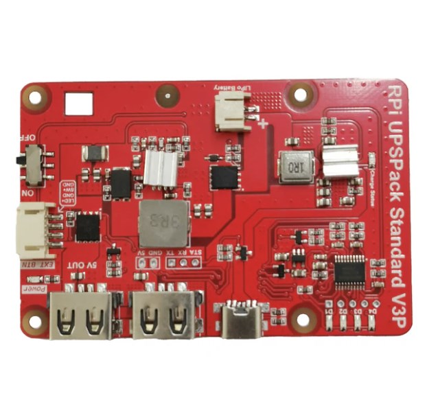

The new version of UPSPack V3 Plus (V3P) is applicable to the whole series of Raspberry Pi.
Added EXT BTN interface to support PH2.0 4P self-locking switch with LED.
Generally speaking, users do not need to solder headers,
and only need to connect the power cord to achieve uninterrupted power supply (the external power supply
is disconnected, and the battery is uninterrupted power supply,
which does not affect the operation of the Raspberry Pi).
It is only needed when the GPIO power supply is needed soldering the 2P pin header,
or use the Raspberry Pi serial port to communicate,
and only solder the 3PIN pin header when developing new products.
If you need to solder the headers, please test the basic functions
when you receive the product before soldering the headers.
UPS board size: length 86.02mm x width 56.02mm x height 10mm
(height: measured at the highest protruding position of the component, excluding battery height)
Be careful not to buy the wrong battery size, only 4000 mAh battery is smaller than the UPS motherboard,
and other capacities are larger than UPS:
Model Volume (Length x Width x Thickness)
4000mAh: 70mm x 41mm x 9.5mm
10000mAh: 115mm x 65mm x 9mm
Functional characteristics | The RPi UPSPack V3 version | The RPi UPSPack V3P version |
Enter the interface | TYPE-C Interface (power cord compatible with new Pi4) | TYPE-C Interface (power cord compatible with new Pi4) |
Output current | 5V 3A | 5V 3A |
External power failure, Pi continuous power supply (no restart) | Support | Support |
Hardware on and off switch | YES | YES |
GPIO power supply interface and UART, halt signal signal interface | YES | YES |
Lithium battery power statistics | Support | Support |
Turn on low pressure detection | Support | Support |
Abnormal detection of power adapter (power outage time detection) | Support | Support |
Detection of the output voltage value of the USB-A seat | Support | Support |
Automatic notify shutdown before battery depletion | Support | Support |
After the power failure, the program automatically | Support (no manual intervention, program boot-up) | Support (no manual intervention, program boot-up) |
After the outage switch, the UPS automatically switches to dormant mode | Support | Support |
The EXT BTN interface | It is not supported | Support for the PH2.0 4P self-lock switch button with LED |
Serial Port (UART) communication with Pi: | ||
Communication Settings | 9600 bps 8N1 | 9600 bps 8N1 |
Protocol version number | V3.1(and later, Update) | V3.2(and later, factory-latest) |
Agreement down-down compatibility | Compatible with the older version of the V3 UPS communication protocol | Compatible |
Single Bus Communications between UPS and Pi (System halt signal) | ||
Communication IO mouth | UPS Motherboard STA Interface Connect Raspberry Pi GPIO18 (BCM 18) | UPS Motherboard STA Interface Connect Raspberry Pi GPIO18 (BCM18) |
Communication protocol | Pulse mode | The level mode |
Software compatibility | V3,v3P is more reliable with pulse detection (not compatible with V2 version of software) | Method of level detection |
Test method:
1. All the above data units are hours (hours).
2.The running system is: 2020-05-27-raspios-buster-full-armhf, and the system does not modify any settings. Only one RPi_runtime_recoder.py is run in the background of the system for time statistics.
3. The three-capacity batteries are fully charged, and then connected to the Raspberry Pi, use the program to record the time. The discharge cut-off point is the UPS to automatically shut down the Raspberry Pi, and the actual running time can be checked through the log file.
4. Download and run UPSPACK_V3/time_count/RPi_runtime_recoder.py for time recording. After the Raspberry Pi is shut down, plug in the power adapter to read the time_log.txt in the program directory to check the battery life.
Hardware description
1) Interface Description

| NO. | Name | Description |
| 1 | TYPE-C Power Adapter Charging Interface | The interface for external 5V power supply to supply power to the UPS, the power supply needs 5V 2A-3A |
| 2 | USB-A Socket | Two USB-A sockets supply power to the Raspberry Pi motherboard. |
| 3 | LED Battery Indicator | 4 LED lights (D1-D4) are used to indicate the current power of the lithium battery |
| 4 | UPS Board Test Port | The factory is used to burn the UPS program and automatically test the motherboard. This interface is useless to the user. |
| 5 | MCU Controller | Used for charging and discharging path management, communication with Raspberry Pi motherboard and other functions. |
| 6 | Double PMU(Power Manage Unit) | 2 batteries charge and discharge, path management chip (chip is encrypted) |
| 7 | PH2.0 Lithium Battery Input Interface | Support 1S 3.7V lithium battery, compatible with 3.7V 18650/21700 battery pack (requires battery pack rated voltage to be 3.7V) |
| 8 | UPS Output Switch | ON / OFF switch, when the switch is turned ON, the UPS will output 5V to the Raspberry Pi motherboard. The opposite is true for OFF. (External power failure and low battery voltage, the program will automatically turn off the power output) |
| 9 | 2.54mm Pin Header | 3P pin header: single-wire communication and UART interface, used to connect to the GPIO port of the Raspberry Pi motherboard for communication. |
| 2P power port: 5V power supply through the Raspberry Pi GPIO power port. | ||
| The product comes with a pin header by default, if the player needs to use the above interface, they can selectively solder. | ||
| 10 | Power Output LED Light | When the output 5V is stable, the green LED lights up. |
| 11 | PH2.0 Interface | EXT BTN means that it can be connected to a self-locking switch button with LED lights |